Networking

Checking MTU from a remote client without having to talk to anyone

Posted by robd on January 02, 2020
Networking / No Comments

We suspected we had some MTU issues at one of our remote sites and as a 3rd line engineer I don’t often have to talk with users and after a while you get in the habit of not talking to users which leads to never wanting to talk to users. – Note you’ll need admin access to the users machine.

So here’s a little guide to run tests from users computers without having to call and talk to them.

First download and put it somewhere you can cmd too on your machine.

https://docs.microsoft.com/en-us/sysinternals/downloads/psexec

Optional – Then download this if you for example want to test MTU.

https://elifulkerson.com/projects/mturoute.php

Next copy the MTUroute software to the user’s computer.

Next from your computer run the below command which will remotely execute mturoute.exe to test the MTU to 192.168.1.5 on UsersComputer:

PsExec.exe \\UsersComputer C:\temp\mturoute.exe 192.168.1.5

Tags: ,

SNMP v3 – Cisco Catalyst 9500

Posted by robd on August 07, 2019
Networking / No Comments

Had this frustrating issues with a Cisco Catalyst 9500 and enabling SNMP with AES 256.

Basically 256 AES encryption wont wor:

snmp-server user USER1 GROUP1 v3 auth sha PASSWORD1 priv aes 256 PASSWORD2
snmp-server group GROUP1 v3 priv

But these would:

snmp-server user USER1 GROUP1 v3 auth sha PASSWORD1 priv aes 128 PASSWORD2
snmp-server group GROUP1 v3 priv

To test I used following software:

Paessler SNMP Tester:

This is it working:

Paessler SNMP Tester 5.2.3 Computername: COMPUTER Interface: 192.168.1.2

07/08/2019 09:17:20 (2 ms) : Device: 192.168.1.1

07/08/2019 09:17:20 (3 ms) : SNMP V3

07/08/2019 09:17:20 (4 ms) : Uptime

07/08/2019 09:17:22 (2244 ms) : SNMP Datatype: ASN_TIMETICKS

07/08/2019 09:17:22 (2250 ms) : -------

07/08/2019 09:17:22 (2256 ms) : DISMAN-EVENT-MIB::sysUpTimeInstance = 300185783 ( 34 days )

07/08/2019 09:17:23 (2521 ms) : SNMP Datatype: SNMP_EXCEPTION_NOSUCHOBJECT

07/08/2019 09:17:23 (2523 ms) : HOST-RESOURCES-MIB::hrSystemUptime.0 = No such object (SNMP error # 222) ( 0 seconds )

07/08/2019 09:17:23 (2524 ms) : Done

This is it broken:

Paessler SNMP Tester 5.2.3 Computername: COMPUTER Interface: 192.168.1.2
06/08/2019 12:22:13 (2 ms) : Device: 192.168.1.1
06/08/2019 12:22:13 (3 ms) : SNMP V3
06/08/2019 12:22:13 (4 ms) : Uptime
06/08/2019 12:22:18 (4237 ms) : SNMP Datatype: ASN_PRIMITIVE
06/08/2019 12:22:18 (4242 ms) : -------
06/08/2019 12:22:18 (4245 ms) : DISMAN-EVENT-MIB::sysUpTimeInstance = No response (check: firewalls, routing, snmp settings of device, IPs, SNMP version, community, passwords etc) (SNMP error # -2003) ( 0 seconds )
06/08/2019 12:22:22 (8462 ms) : SNMP Datatype: ASN_PRIMITIVE
06/08/2019 12:22:22 (8466 ms) : HOST-RESOURCES-MIB::hrSystemUptime.0 = No response (check: firewalls, routing, snmp settings of device, IPs, SNMP version, community, passwords etc) (SNMP error # -2003) ( 0 seconds )
06/08/2019 12:22:22 (8468 ms) : Done


Tags: , ,

iPerf

Posted by robd on May 08, 2019
Networking / No Comments

I’ve been running iperf a lot recently, which is a tool to measure TCP, UDP and bandwidth performance across a network.  I’ve been running this specially from the users computer to a local server i.e. not across a WAN or MPLS etc.

The users computer has a 1GB connection to the switch and from there the switch is connected to the server via a 10GB NIC.

On the server I ran:

iperf3.exe -S

On the client I ran:

iperf3.exe -c 10.52.7.73 -R

Below are my initial results, as you can see the connection is nearly maxing out its 1GB connection:

[ ID] Interval           Transfer     Bandwidth

[  4]   0.00-10.00  sec  1.10 GBytes   942 Mbits/sec             sender

[  4]   0.00-10.00  sec  1.10 GBytes   941 Mbits/sec             receiver


I then ran the same test but increasing the TCP connections to better simulate a heavy network application.  From the screen shot below the network is performing well.

iperf3.exe -c 10.52.7.73 -R -P 20

So what do all the switches mean:

-t  option used in the above command tells to transfer data for 20 seconds.

-w will specify your desired window size value.  Whenever two machines are communicating with each other, then each of them will inform the other, about the amount of bytes it is ready to receive at one time. In other words, the maximum amount of data that a sender can send the other end, without an acknowledgement is called as Window Size.

-P 20 will increase the number of parallel TCP connections i.e. to 20 (Parallel TCP connections).

-R enabled reverse connections to and from the server

-I Changes the interval between periodic bandwidth tests. For example, -i 60 will make a new bandwidth report every 60 seconds. The default is zero, which performs one bandwidth test.

-B Binds iPerf to a specific interface or address. If passed through the server command, the incoming interface will be set. If passed through the client command, the outgoing interface will be set.

-i {time in seconds} #### update interval on screen; default is 1 second. Can be useful when running large numbers of concurrent tests to increase the interval, or disable with “-i 0”

–logfile {filename} #### outputs what would normally be in your terminal to a log file of your choosing.


Want to test QoS?  Specifically EF, then is the is bad boy:

iperf3.exe -c 10.52.7.73 -w 1M -P 5 -t 60 -R -i 5 -S 0xB8


Tags: , ,

How to setup Cisco port mirroring to a VM

Posted by robd on December 06, 2017
Networking, vmware / 1 Comment

Today we needed to mirror a port on a Cisco switch in a country far far away meaning we couldn’t just wander down with a laptop.

So to get around this we decided to mirror the port to a VM that’s on site, here’s how we did it:

There’s two switches between the VM and the port we want to mirror so first we have to setup the port mirroring on every switch using RSPAN (Remote Switched Port Analyser) and a new vlan.

Add an RSPAN vlan to both the switch with the port to mirror, and to the switch that has the packet capture device on.

Conf t
Vlan 9999
Remote-span

Then make sure that RSPAN vlan is trunked between the 2 switches and on the VMWARE interface.

switchport trunk allowed vlan add 9999

Assuming the following;

You use vlan 999 for the RSPAN vlan.

The port you want to mirror is on switch 1 port g1/0/2.

You want to send the mirrored traffic to switch 2 port 1/0/23 (the port that connects to VMWARE).

You are going to use monitor session 1 on both switches. (this can be any session number between 1-66, and can be different on each switch).

On Switch 1 (mirror port 2 and punt out the traffic to 9999)

Conf t
Monitor session 1 source interface g1/0/2 both
Monitor session 1 destination remote vlan 999

On Switch 2 (suck in all traffic from 9999 and punt it to port 23)

Conf t
Monitor session 1 source remote vlan 999
Monitor session 1 destination interface g1/0/23

You can see that the monitoring is set up with;

Show monitor session

Network Diagram:

Next, we need to do the VMware side of things:


Setup a new port group on a vswitch:

Although we chose vlan 9999 when its pushed to the new port it will not be tagged so choose all:

Next edit the port group and allow Promiscuous mode, this will allow traffic not destined for the VMs MACs (normal behaviour, any traffic not destined to a VM MAC will be dropped):

Add a NIC to your VM using the port group:

Don’t worry about a IP etc:

Fire up Wireshark:

Look at all these glorious packets:


Tags: , , , ,

HP SAN P4300 Performance

Posted by robd on April 04, 2014
Networking, SAN, Server / No Comments

We had some issues a while back where there was latency between a PC and SAN so I started to look at all the layers to try and find a problem, here’s my findings in case anyone finds it a interesting read.

To rule out the PC, I’ve tested the performance of the SAN and network throughput.

The performance of the SAN which is based in IOP’S (Input/Output Operations Per Second) and the current average total is 800 (found on the SAN info page).  To put this prospectus, a poor performance would be in the 2000’s.

The below graph only shows output from 17:28 but has been running all day meaning the average should be accurate:

SAN1

Looking at the performance of switches can be difficult, but we’ve started using HP Intelligent Management Centre which is great at collating stats. The switches reported low bandwidth, CPU, memory and I/O seemed normal:

Switch1

We know from experience the throughput on these switches is limited by infrastructure in our case 1GB fibre.

These are the theoretical Max Sequential (SEQ) write limits we could obtain from our connection to the SAN (in practice there is a  5%-20% overhead involved):

SAN2

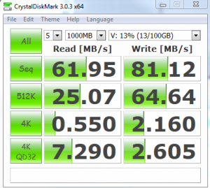
I’ve managed to very roughly test this write limit from a client to the SAN SAS disks:

SAN3

A result of 81.12MB/s is very positive, considering we can realistically over ever achieve 125MB on our current setup.

What this meant in my opinion was the SAN and network were not to blame meaning it was either client or server….Long story short the AV on the server was causing our latency not the “network”.

Tags: , , , ,

HP Switch – Access control Lists

Posted by robd on April 04, 2014
Networking / 1 Comment

Hi All,

We’ve recently implemented a BYOD wireless SSID for end users to check facebook or what ever it is they do.  As we’re short on resources we had to use existing DC’s to doll out IP’s but we were obviously worried around users “hacking” into the system.  So first thing we did was create a VLAN and assigned it to the wireless then applied several access control lists (ACL’s) to the core switch limiting the access to only the DC’s, proxy, core switch, each other and firewall then blocked the rest:

Firstly check the subnet mask of the VLAN you want to apply the ACL too as the wildcard/subnet address in the ACL will change dependant of the subnet.

The below example will use a subnet mask of 255.255.255.0 (the bits in red are notes only – do not try and apply them)

Logon to a switch and go into config mode:

#Here we specify the ACL will be extended rather than standard then we create a name for the ACL 
ip access-list extended NEWACL      
#The below rules specify what servers the users on the ACL  can have access too:
10 permit ip 192.168.241.0 0.0.0.255 192.168.250.2 0.0.0.0
15 permit ip 192.168.241.0 0.0.0.255 192.168.250.3 0.0.0.0
20 permit ip 192.168.241.0 0.0.0.255 10.0.0.1 0.0.0.0
25 permit ip 192.168.241.0 0.0.0.255 192.168.250.18 0.0.0.0
30 permit ip 192.168.241.0 0.0.0.255 10.0.0.76 0.0.0.0
31 permit ip 192.168.241.0 0.0.0.255 192.168.241.254 0.0.0.0
35 permit ip 192.168.241.254 0.0.0.0 0.0.0.0 255.255.255.255
#The below denies access to certain subnets
50 deny ip 192.168.241.0 0.0.0.255 192.168.0.0 0.0.255.255
55 deny ip 192.168.241.0 0.0.0.255 10.0.0.0 0.255.255.255
57 deny ip 192.168.241.0 0.0.0.255 172.0.0.0 0.255.255.255
#This final permit allows access to itself and therefor out of its network to other networks:
60 permit ip 192.168.241.0 0.0.0.255 0.0.0.0 255.255.255.255
#Apply this ACL to a vlan, in this case 3241:
VLAN 3241 ip access-group NEWACL in
#Show me my handy work:
Show Access-List GuestACL


Finally test!

Ok so what if you have a network that has a subnet of 255.255.252.0, well the wildcard changes in the ACL or above we had 0.0.0.255 where as in a 255.255.252.0 subnet we’d need 0.0.3.255.

Example:

#Name of ACL and extended:
ip access-list extended "StudentACL1"
#List of allowed servers:
10 permit ip 192.168.216.0 0.0.3.255 192.168.250.2 0.0.0.0
15 permit ip 192.168.216.0 0.0.3.255 192.168.250.3 0.0.0.0
20 permit ip 192.168.216.0 0.0.3.255 10.0.0.1 0.0.0.0
25 permit ip 192.168.216.0 0.0.3.255 192.168.250.18 0.0.0.0
26 permit ip 192.168.216.0 0.0.3.255 192.168.250.30 0.0.0.0
27 permit ip 192.168.216.0 0.0.3.255 192.168.250.68 0.0.0.0
30 permit ip 192.168.216.0 0.0.3.255 10.0.0.76 0.0.0.0
31 permit ip 192.168.216.0 0.0.3.255 192.168.216.254 0.0.0.0
35 permit ip 192.168.216.254 0.0.0.0 0.0.0.0 255.255.255.255
#List denied subnets:
50 deny ip 192.168.216.0 0.0.3.255 192.168.0.0 0.0.255.255
55 deny ip 192.168.216.0 0.0.3.255 10.0.0.0 0.255.255.255
57 deny ip 192.168.216.0 0.0.3.255 172.0.0.0 0.255.255.255
#Apply to this VLAN:
VLAN 3216 ip access-group StudentACL1 in
#Show me the money:
Show Access-List StudentACL1
Save


So what happens if you want to delete a ACL from a VLAN:

#remove the ACL from the VLAN: 
no VLAN 3216 ip access-group StudentACL in
#Remove the ACL from the switch:
no ip access-list extended StudentACL
Save
#Now to check its gone either do Show Access-List or Show Config.


Tags: , , , , ,

IP Routes

Posted by robd on March 29, 2014
Networking / No Comments

Hi All,

Started at a new company recently and they’ve had a ongoing issues for ages where they could only access one of two switches in their server room if they were on the same subnet.

So Switch A was the problem switch and had a IP of 10.0.0.123,

Switch B they could access from anywhere and had a IP of 10.0.0.124.

My Computer had a IP of 192.168.111.1.

So initially I started thinking the issue was down to vlans as we have around 50 vlans and I kind of just presumed it would be a issue with cross vlan routing.  Well actually I was wrong.

Firstly I pinged both switches:

SwicthA – Can not ping.

SwitchB – Can ping.

Next Trace route (TraceRT from a win 7 PC)

SwitchA – Could not trace

SwitchB – two hop trace, Core switch then the switch.

Ok so what next…..Lets try the above from the switches (so after connecting to server on the same subnet I ran the tests):

Ping my PC:

SwicthA – could not ping,

SwitchB – could ping.

Trace route:

SwitchA – No route,

SwitchB – two hop route.

So after this I decided it must be a routing issue, as both switches could ping the core switch and both switches could trace route the core switch.  So lets have a butchers at the routing.

Switch A# show ip route

                                IP Route Entries

  Destination        Gateway         VLAN Type      Sub-Type   Metric     Dist.
  ------------------ --------------- ---- --------- ---------- ---------- -----
  10.0.0.0/8         DEFAULT_VLAN    1    connected            1          0
  127.0.0.0/8        reject               static               0          0
  127.0.0.1/32       lo0                  connected            1          0
  192.168.101.0/24   iSCSI-VLAN      1010 connected            1          0
Switch B# show ip route

                                IP Route Entries

  Destination        Gateway         VLAN Type      Sub-Type   Metric     Dist.
  ------------------ --------------- ---- --------- ---------- ---------- -----
  0.0.0.0/0          10.0.0.2       1    static               250        1
  10.0.0.0/8         DEFAULT_VLAN    1    connected            1          0
  127.0.0.0/8        reject               static               0          0
  127.0.0.1/32       lo0                  connected            1          0
  192.168.101.0/24   iSCSI-VLAN      1010 connected            1          0


Hold the phone, there’s no sodding return route to the core switch (10.0.0.2)

So I added the route like so:

Switch B# conf
Switch B (conf)# ip route-static 0.0.0.0 0.0.0.0 10.0.0.2
Switch B# write

And bobs your uncle it worked!!


Tags: , , , ,

HP Swicth – Show everything to a TFTP Server

Posted by robd on March 27, 2014
Networking / No Comments

So How do I send the output of the “show tech all ” command to a TFTP server?

Easy.

Launch the TFTP server (i.e. TGTPD64 from HERE), and issue this command at the CLI of the switch:

  copy command-output 'show tech all' tftp <IP addr of TFTP server> <destination filename>.txt

Tags: , , ,

Force traffic through a Network interface

Posted by robd on November 06, 2012
Networking / No Comments

Occasionally you may want to force traffic through a specific network interface.

For example, you have a VPN and you don’t want Chrome or IE (really, you use IE?)  to use the VPN as its slow and certain web sites may be restricted (because you shouldn’t be looking at facebook all day!)!

So what you need to do is change the network interface for the VPN to have a HIGH metric in the Advanced properties of the Networking interface.

This will force all traffic through your other network connection BUT and this is a big BUT, do the below after you have connected to what ever it is you want to connect to via your VPN (does that make sense? if not let me know in the comments)!

Turn your machine on, connect to the internet and then connect to the VPN, connect to what ever it is you do on your VPN,

Then Go to Network connections

Properties of undesirable network interface (VPN in this case but could be a Ethernet connection if you want to use your wireless for internet rather than Ethernet)

Properties > Double Click Internet Protocol Version 4 > Advanced

Deselect Automatic Metric

and enter a high number like 500

Ok Out,

and open Chrome or IE or what ever and check the IP to see what interface your routing out off!


Done

Tags: , , , , ,

ESX Gateway Host entry

Posted by robd on August 08, 2012
ESX, vSphere / No Comments

Had an annoying error today while trying to add a ESX 4.1 host to DataCenter:

Call “datacenter.queryconnectioninfo” for object “DC or Cluster Name” on vCenter Server “vCenter” failed.

Firstly I thought my password may be wrong for the host, it wasn’t!

Then, maybe my new host is in maintenance mode, it wasn’t!

Finally, and really it should of been obvious to me:

I’d changed the IP address twice while building the box via the console and had forgotten to enter a new default gateway!

So jumped on vSphere for the new host,
clicked the Configuration tab,
clicked Networking,
clicked properties (the one next to Virtual Switch: vSwitch0),
click Service Console and edit,
click Continue modifying this connection..,
clicked IP settings and
Added a Service Console Default Gateway! OK’d out

And Bam, added the host to the Datacenter!!

Tags: , , ,